

The MEP (Mechanical/Electrical/Plumbing) Modeler is an integral extension to ARCHICAD and now included free. Architectural practices and architectural departments of A/E firms using ARCHICAD can use MEP Modeler to create, edit or import 3D MEP networks (ductwork, piping and cable trays) and coordinate them within ARCHICAD.
The Graphisoft MEP Modeler™ can be used in the following workflows:
BIM Workflow – Where the MEP engineer can provide 3D data, architects are able to import the consultant’s MEP model into ARCHICAD using the IFC format. In addition to this generic IFC interface, the MEP Modeler package provides an improved connection with AutoCAD® MEP via IFC format, using an export plug-in called ARCHICAD Connection.
2D Workflow – Based on 2D documentation received from engineers, architects can use the powerful built-in tools to create and edit the MEP model within ARCHICAD
Its powerful modeling & coordination capabilities in combination with the above workflows make the MEP Modeler the solution for architects to help drive more efficiency in the building process.
The MEP Modeler consists of a rich set of capabilities in the areas for modeling, editing and coordination:
MEP Toolbox
The MEP Toolbox provides a dedicated set of tools to create components of the various MEP systems:
-
Straight segments of HVAC ducts, pipes and electrical cable trays
-
Transitions, junctions, in-line elements to connect MEP components with each other
-
Equipment and terminals for automatic connection at the intake and the output locations of the MEP systems.
- MEP elements are parametric for easy configuration of custom dimensions.
MEP Library
The Graphisoft MEP Modeler ships with a rich MEP specific object library. This library contains specially configured MEP elements that include smart connection points for automatic connection during routing of MEP systems. All relevant standard ARCHICAD objects will be extended with smart connection points as well as specific MEP related parameters.
MEP Systems
The MEP Modeler uses MEP systems to represent a group of elements that are handled together, making the creation and editing much more efficient and consistent. MEP systems, such as ducts, pipes and cable trays control certain attributes of elements belonging to the same system. System level attributes such as contour pens, system materials and centerlines define the look of entire systems, helping with identification. When new elements are added to an existing MEP system, they will automatically take on the appropriate connection parameters such as shape and diameter as well as width and height values.
Smart MEP Routing
MEP systems can be created with ease using the MEP Routing function. Individual MEP elements are placed automatically along the defined route based upon certain preset rules. Routing is available in the floor plan and the 3D window. ARCHICAD’s smart cursor and guide lines enable designers to create connected MEP elements with a series of mouse-clicks from scratch, quickly and easily. The 3D route of the system and the individual elements can be modified at any time.
Editing MEP elements
A powerful set of graphical editing aids to modify the geometry of individual MEP elements of MEP systems is provided. Editing a part of an MEP system will automatically change connected elements. New connector elements may be also be added to the system.
Creating custom MEP elements
Custom MEP elements using standard ARCHICAD tools such as Walls, Slabs and GDL Objects including any MEP elements may be created and saved. These custom library parts will be automatically added to the current MEP library. They may be placed into the project or may later be re-used in other projects. Custom created MEP elements have the same smart behavior as the standard MEP library parts shipped with the MEP Modeler.
Automatic Collision Detection
This capability provides a unique, fully automated routine to identify and visualize conflicts between the architectural design and the MEP network. Collision detection of the MEP system against the building structure ensures fast and precise feedback for the architect and streamlines coordination with the building engineering team.
MEP Collision Detection identifies the exact location of discrepancies on the floor plans and the 3D views. All collision entries are automatically added Mark-Up Palette, providing easy identification. Designers can quickly evaluate these entries one-by-one and identify their location in the design with a single click. Discussions can be conducted between the members of the extended design team to evaluate alternative solutions, using ARCHICAD’s Mark-Up tools.
Collaboration with Engineers
In addition to traditional 2D workflows, MEP systems can be directly imported into ARCHICAD from Autodesk AutoCAD MEP and Revit applications. All AutoCAD MEP systems are identified and automatically converted to native ARCHICAD MEP elements. The ARCHICAD Connection plug-in can be installed free in Autodesk applications to facilitate the communication between the programs. Engineers can then export their MEP design using the connection plug-in, and architects can import the MEP designs as smart ARCHICAD elements.
Sharing and Visualizing the MEP Model
ARCHICAD’s extensive export capabilities enable designers to output files in different modeling formats including the industry standard IFC 2×3 format for coordination using external applications.
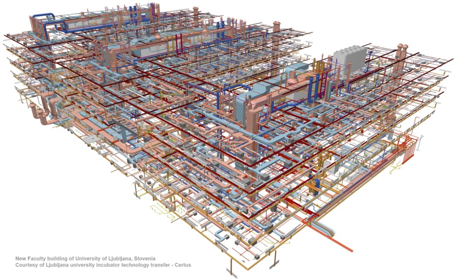
The ability to visualize MEP systems in the complete building environment improves communication between architects, engineers and contractors. Visualization can be done within ARCHICAD using color codes for the various mechanical systems in combination with wireframe representation of the architectural structures. ARCHICAD’s powerful rendering capabilities can be used to create photo-realistic visualizations of systems for the different trades.
